Thermodynamic cycle
| Thermodynamics | ||||||||

| ||||||||


State properties depend only on the thermodynamic state, and cumulative variation of such properties add up to zero. Path quantities, such as heat and work are process dependent, and cumulative heat and work are non-zero. The first law of thermodynamics dictates that the net heat input is equal to the net work output over any cycle. The repeating nature of the process path allows for continuous operation, making the cycle an important concept in thermodynamics. Thermodynamic cycles often use quasistatic processes to model the workings of actual devices.

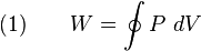

If the cyclic process moves clockwise around the loop, then it represents a heat engine, and W will be positive. If it moves counterclockwise then it represents a heat pump, and W will be negative.
Abstract
Two primary classes of thermodynamic cycles are power cycles and heat pump cycles. Power cycles are cycles which convert some heat input into a mechanical work output, while heat pump cycles transfer heat from low to high temperatures using mechanical work input. Cycles composed entirely of quasistatic processes can operate as power or heat pump cycles by controlling the process direction. On a pressure-volume or Temperature-entropy diagram, the clockwise and counterclockwise directions indicate power and heat pump cycles, respectively.[edit] Thermodynamic power cycles
Main article: Heat engine
Thermodynamic power cycles are the basis for the operation of heat engines, which supply most of the world's electric power and run almost all motor vehicles. Power cycles can be divided according to the type of heat engine they seek to model. The most common cycles that model internal combustion engines are the Otto cycle, which models gasoline engines and the Diesel cycle, which models diesel engines. Cycles that model external combustion engines include the Brayton cycle, which models gas turbines, and the Rankine cycle, which models steam turbines. 


Thermodynamic heat pump and refrigeration cycle
Main article: Heat pump and refrigeration cycle
Thermodynamic heat pump and refrigeration cycles are the models for heat pumps and refrigerators. The difference between the two is that heat pumps are intended to keep a place warm while refrigerators are designed to cool it. The most common refrigeration cycle is the vapor compression cycle, which models systems using refrigerants that change phase. The absorption refrigeration cycle is an alternative that absorbs the refrigerant in a liquid solution rather than evaporating it. Gas refrigeration cycles include the reversed Brayton cycle and the Hampson-Linde cycle. Regeneration in gas refrigeration allows for the liquefaction of gases.Types of thermodynamic cycles
A thermodynamic cycle can (ideally) be made out of 3 or more thermodynamic processes (typically 4). The processes can be any of these:- isothermal process (at constant temperature, maintained with heat added or removed from a heat source or sink)
- isobaric process (at constant pressure)
- isometric / isochoric process (at constant volume)
- adiabatic process (no heat is added or removed from the working fluid)
- isentropic process, reversible adiabatic process (no heat is added or removed from the working fluid - and the entropy is constant)
- isenthalpic process (the enthalpy is constant)
| Cycle | Process 1-2 (Compression) | Process 2-3 (Heat Addition) | Process 3-4 (Expansion) | Process 4-1 (Heat Rejection) | Notes |
|---|---|---|---|---|---|
| Power cycles normally with external combustion - or heat pump cycles: | |||||
| Bell Coleman | adiabatic | isobaric | adiabatic | isobaric | A reversed Brayton cycle |
| Brayton | adiabatic | isobaric | adiabatic | isobaric | Jet engines aka first Ericsson cycle from 1833 |
| Carnot | isentropic | isothermal | isentropic | isothermal | |
| Diesel | adiabatic | isobaric | adiabatic | isometric | |
| Ericsson | isothermal | isobaric | isothermal | isobaric | the second Ericsson cycle from 1853 |
| Scuderi | adiabatic | variable pressure and volume | adiabatic | isometric | |
| Stirling | isothermal | isometric | isothermal | isometric | |
| Stoddard | adiabatic | isobaric | adiabatic | isobaric | |
Power cycles normally with internal combustion: | |||||
| Lenoir | isobaric | isometric | adiabatic | isobaric | Pulse jets (Note: 3 of the 4 processes are different) |
| Otto | adiabatic | isometric | adiabatic | isometric | Gasoline / petrol engines |
| Brayton | adiabatic | isobaric | adiabatic | isobaric | Steam engine |
Ideal cycle

- TOP and BOTTOM of the loop: a pair of parallel isobaric processes
- LEFT and RIGHT of the loop: a pair of parallel isochoric processes
Carnot cycle
Main article: Carnot cycle
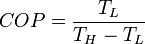
The Carnot cycle is a cycle composed of the totally reversible processes of isentropic compression and expansion and isothermal heat addition and rejection. The thermal efficiency of a Carnot cycle depends only on the temperatures in kelvins of the two reservoirs in which heat transfer takes place, and for a power cycle is:

Otto cycle
Main article: Otto cycle
An Otto cycle is constructed out of:- TOP and BOTTOM of the loop: a pair of quasi-parallel adiabatic processes
- LEFT and RIGHT sides of the loop: a pair of parallel isochoric processes
Diesel cycle
Main article: Diesel cycle
A Diesel cycle is constructed out of:- TOP and BOTTOM of the loop: a pair of quasi-parallel adiabatic processes
- LEFT side of the loop: an increasing volume isobaric process
- RIGHT side of the loop: an isochoric process
Scuderi cycle
Main article: Scuderi cycle
A Scuderi cycle is constructed out of:- TOP and BOTTOM of the loop: a pair of quasi-parallel adiabatic processes
- LEFT side of the loop: a positively sloped,increasing pressure, increasing volume process
- RIGHT side of the loop: an isochoric process
Stirling cycle
Main article: Stirling cycle
A Stirling cycle is like an Otto cycle, except that the adiabats are replaced by isotherms. It is also the same as an Ericsson cycle with the isobaric processes substituted for constant volume processes.- TOP and BOTTOM of the loop: a pair of quasi-parallel isothermal processes
- LEFT and RIGHT sides of the loop: a pair of parallel isochoric processes
State functions and entropy
If Z is a state function then the balance of Z remains unchanged during a cyclic process: .
.

 ,
,

References
- Halliday, Resnick & Walker. Fundamentals of Physics, 5th edition. John Wiley & Sons, 1997. Chapter 21, Entropy and the Second Law of Thermodynamics.
ไม่มีความคิดเห็น:
แสดงความคิดเห็น